They have not made it in a while but may do it to order, if there is enough demand.

Boost Gauge
With a lot of modern turbo charged cars one of the most common
gauges on the dash is a turbo pressure boost gauge.
Why Audi didn't fit a boost gauge to a sports car like the TT is any ones guess.
So apart from a fancy moving dial that provide the dash with a bit more animation, WHY would you want to fit one?
The whole turbo system around the TT engine relies on a sealed vacuum system that controls the turbo pressure, the fuel pressure regulation, the diverter valve opening and the turbo wastegate.
With a healthy car you can get used to the optimum Vacuum and
Pressures
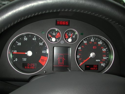
e.g. for mine (in bar) -0.77 vacuum deceleration, -0.60 at idle, 1.4 nominal, 1.7 peak.
With these figures a boost gauge will give you an additional warning of problems that may be impending.
If the boost pressure is too high then perhaps a diverter valve or wastegate is malfunctioning, If the boost is too low then perhaps there is a leak in the vacuum system or again a DV failure, either issue could lead to engine troubles and boost gauge will give the advantage of an early warning of problems to get looked into.
It can also be used to assist in economical driving if that's
your bag
by driving while keeping the boost pressure -ve you can use it as a pseudo
economy gauge.
Its also pretty funky to have one! ;o)
So what options are there?
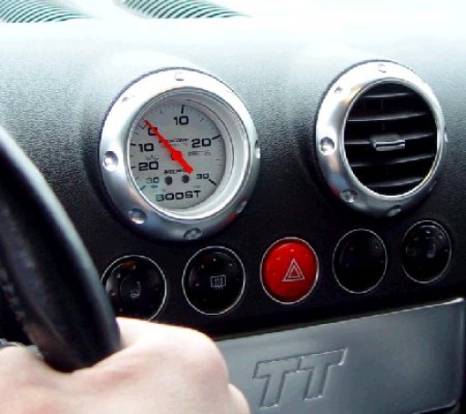
Forge Motorsport produced a TT specific model which was nice but it wasn't
popular, I think more because of the image a boost gauge has and that the
benefits are not understood too well.
They have not made it in a while but may do it to order, if there is enough
demand.
A TT enthusiast in the USA, Steve Schwing, made his own up
using a TT ventilation ring.
This looks pretty cool and can be mounted in a variety of places using a
standard guage pod.
APR do a kit to let you mount a boost gauge into one of your
ventilation air vents,
Also a nicely integrated mod however sacrificing a ventilation duct for it.
Ventilation gauge
instructions
I personally wanted a less intrusive a more integrated gauge,
the closest I had seen was the O.CT boost gauge for the S4.
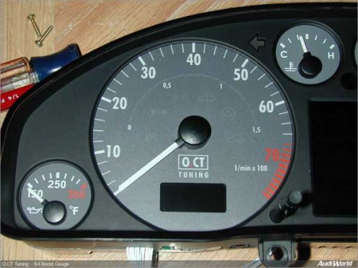

This involves a face change to install the O.CT dial with its subtle row of
LED's behind the display!
However there wasn't a TT version and the risks of pod damage are far far higher
than my eventual solution.
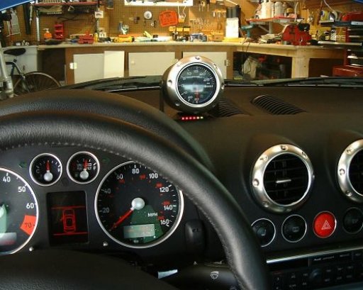
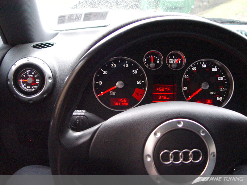
AWE Boost Gauge
A newer development in is the
AWE vent Boost Gauge,
available through AmD
The 2 distinguishing features of the gauge are the colour
scheme matches the TT interior
and it doesn't completely block of the vent so you still get airflow through.

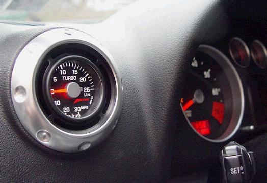
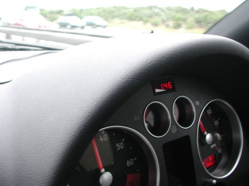
This solution wont suit all but in my driving position I kept
seeing that little grill in the middle of the dash that normally holds the Audi
hands free phone kit microphone and as an unused space it was crying out for a
small boost display.
A little searching and I eventually found a reputable supplier of a natty little
boost gauge which looked a perfect fit and match.
http://www.scottsmototune.co.uk a SKN agent, supplied me with a small 15mm x
35mm gauge with a -2 to +2 bar range..
I had to source a long rigid vacuum pipe (not pictured), a 5mm
T piece and some strong silicone hose make a connection with.
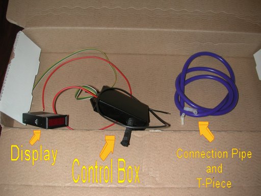
I was initially a little disappointed as it looked a little like a home made
Maplins product and a minor design flaw being there was no connector between the
display and controller and therefore no way to mount the display in a hole using
its bezel.
I first went to AmD and asked them to test its accuracy as the risks of hacking the cable and my dash were worth the effort. AmD checked it and commented on having seen this before, said that it was a very good product which gave me some encouragement.
So I began by cutting the cable and fitting a 4 way PC power
supply male/female connector to separate the display from the controller.
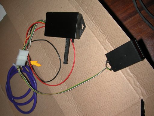
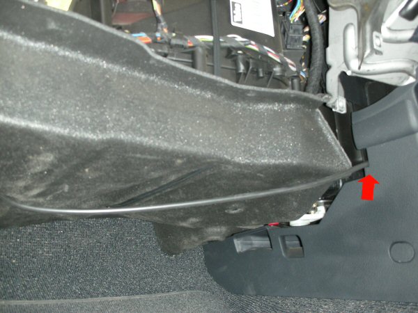
I also cheated, I admit it, I asked AmD to feed the pipe
through from the bulkhead which they did and left the excess coiled pipe in the
passenger foot well ready for me to continue. But for your benefit I have shown
you the path for you to follow.
(or pay AmD the 1/2 hour labour to do it!) :o)
We now do this ourselves at
www.vagcheck.com and follow an oem path using hard boost pipe to the
fuse/relay board area.

So a few weeks later I found the time to start this amongst a busy schedule with the help of JohnB, FHBlue and TTotal providing helpful hands.
So how was it done?
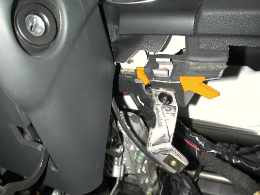
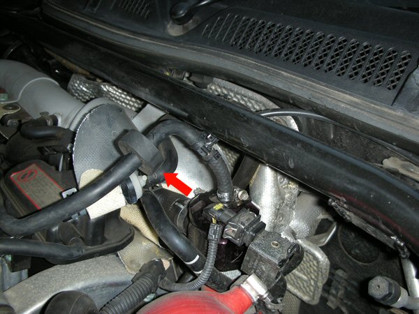
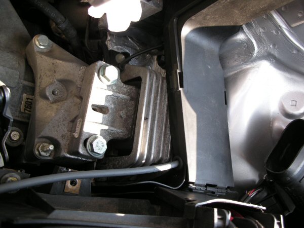
Start by removing the engine cover and finding the fuel pressure regulator, the
pipe leading to it is cut in a sensible place to allow clearance and slack in
the connecting nylon hose to allow for the engine rocking when accelerating
through the gears.
UPDATE NEW TIP:
DONT CUT THE FPR PIPE, Simply remove it from the FPR, put the T-piece in the end
and use a short piece of hose to connect that to the FPR before T-ing off to
your boost gauge.
This makes it much easier to remove if needed in the future.
The 5 mm T-piece is installed and a short piece of silicone
tubing and cable ties are used to connect the (previously fitted) nylon pressure
hose to the T-piece.
The hose path is marked, you could get a black hose if you wanted a more
stealthy install.
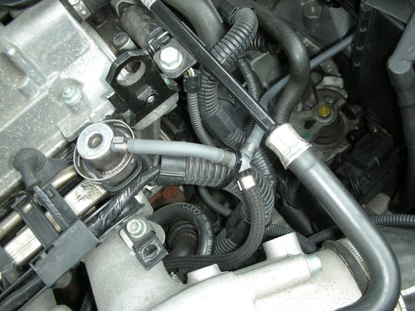
In developing out own installation techniques we follow oem routes with hard
boost pipe when passing through the bulkhead to avoid any chance of compression
in the pipes. Every effort is made to ensure no chaffing or risks to the pipe
work are minimised.
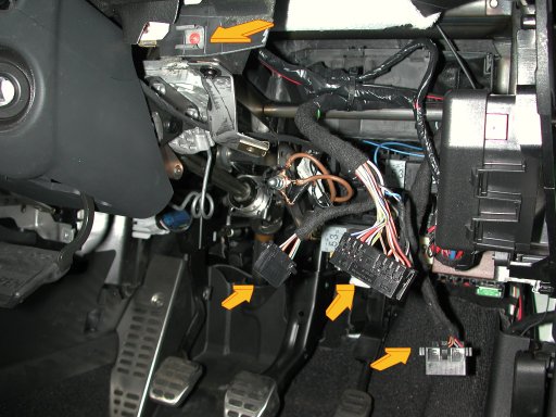
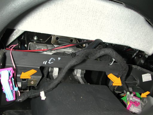
Next Flip open the fuse board cover and remove all the T25
screws.
Remove the 3 lower dash T25 screws
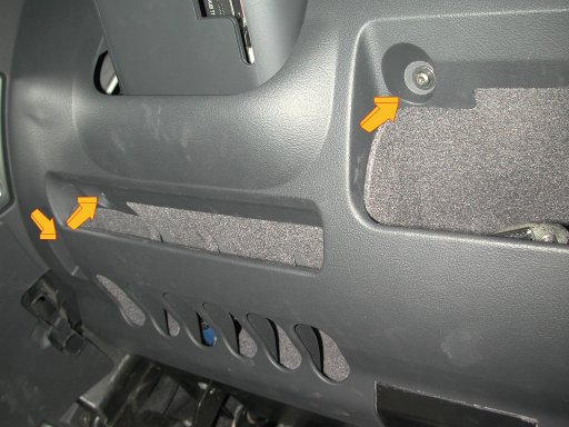
The upper part of the consol is push fitted into 3 clips either side of the steering column
The lower panel has 3 connectors for diagnostic, lights and dimmer which will need to be gently detached.
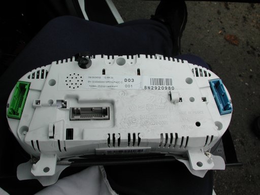
Remove the 2 T25 screws holding the instrument pod, 1 either side of the steering column, these are typically hidden by a small piece of vinyl covering and the lower part of the dash pod will pull forward.
Its best to adjust the steering column to its lowest position and pull back as far as it will go.
The upper part of the dash is simply hooked into the dash, pull the lower part out and push the upper part in to orientate it ready to remove.
There are 3 wiring looms connected,
they have a neat lever mechanism which when gently prised up will pull the connector easily out of the socket.
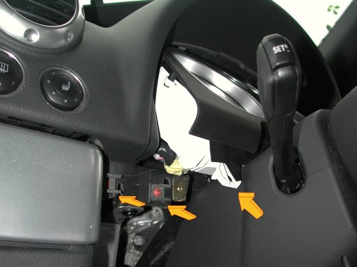
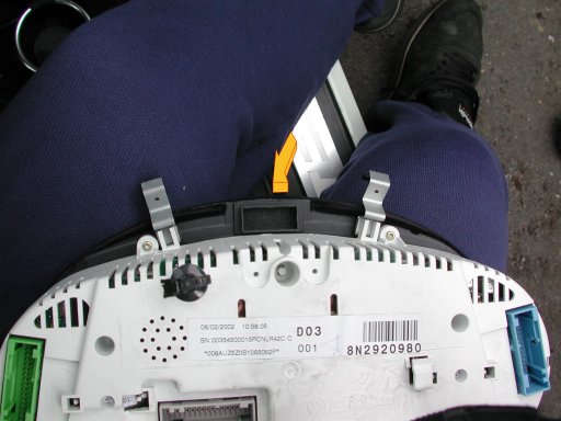
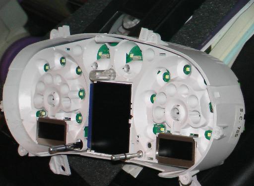
Once the dash is out, the microphone housing can be removed gently, it is glued on from behind
Using a chisel, ease the blade under the edge and gently rock it and work your way round, the plastic is thin and you could end up breaking the fascia so easy and gently and the glue will give.
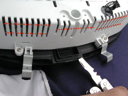
Also take some masking tape and cover the vent holes marked in red.The display fit is excellent vertically but is 2mm too wide, take a file and gently shave off 1mm either side and test so you get a nice tight fit, the masking tape will protect the console from plastic dust.
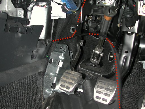
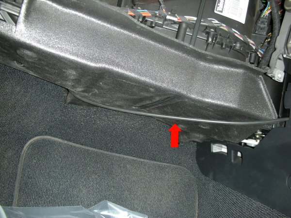
A handy internals Picture WessTTy posted......Then feed the nylon boost hose from behind the centre console up through the dash avoiding any moving parts like pedals and steering columns and cable tie it along the way to avoid rattles.
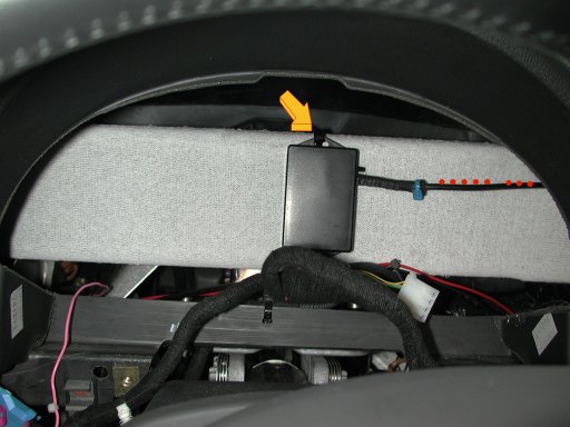
The control unit was cable tied to the visible ventilation duct and power was taken from the fuse box from an ignition switched feed. Cable ties were used on all the hose jointing to ensure they don't come off.
Then Re-fit everything.
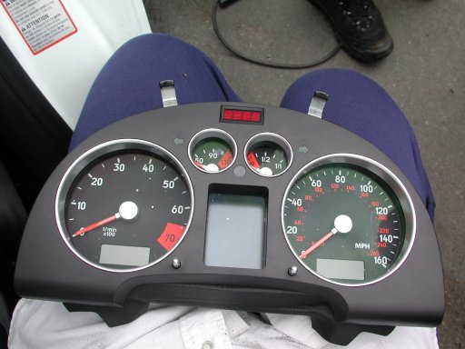
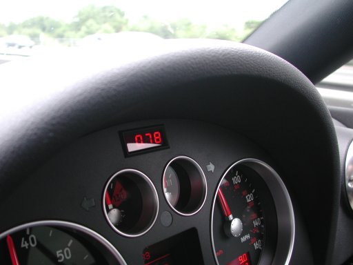
THE END RESULT
Fantastic, the display is great, and fits into the colour scheme really well. Its accurate to the figures quoted by AmD and being digital its much much easier to use and compare reference figures with , I am very pleased with this kit and the fit looks factory installed.DO YOU WANT TO SEE IT IN ACTION? Click HERE!
An interesting detail is when switching the air conditioning on, 0.1 bar boost is lost which I presume translates up the entire boost range when accelerating.Remember www.vagcheck.com can supply and fit you a boost gauge to an extremely high standard, below is available elsewhere if you want to save some money in the short term! ;o)
Comedy Boost Gauge Install
I found this recently...How NOT to install a Boost Gauge.
Do not ignore the original design features like the spacing rubber designed to protect a pipe and then install a segment that raises the pipe to hit the engine cover.
Do not use tiny cable ties on oversize pipes and undersize T-pieces.
Do not fit the t-piece after other valves in the supply chain and then the DV, the FPR is the commonly accepted place to T or any pipe directly off the manifold after all we want to measure what's happening at the manifold.
Do not use this flexible silicone hose and push it through an already tight cable conduit
so its compressed and potentially gives a false reading.
Do not leave boost pipe dangling with no support
Do not let dangling pipes rest against hard plastic edges that will cut through over time.Causes of boost loss:-
Comedy Installs (as Above)
Air Mass Meter failure
N75 Wastegate malfunction
Diverter valve malfunction
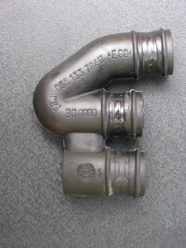
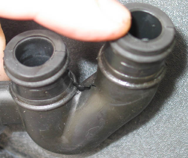
A physical leak.....This pipe sits along side the intake manifold and can split, it not only controls boost but a leak can cause low pressure in the braking system.
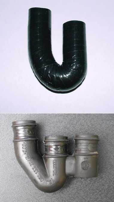
Forge market a replacement hose for around £20
Part No: FMTB1302
Quote Forge :- If you look at the two images above you will see that the replacement hose replicates the OEM vacuum hose. The extra piece of hose on the right hand side of the OEM hose, is not actually used as a hose but slips over the solid vacuum pipe as a pipe holder.
The Forge-Samco hose is sold as a repair hose which is tape bound for extra strength and replaces the damaged OEM unit without the need to replace the entire vacuum pipe system, which is necessary if you were to try to buy the OEM part.